Integrating 3D models with photography
Interested in integrating your 3D work with the real world? This might help
# 1 24-08-2011 , 06:53 PM
ipatch's Avatar
Subscriber
Join Date: Aug 2011
Posts: 24

Polygon Modeling with curves

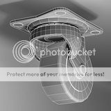
I am really new to modeling with Maya, so please forgive me if I make a few mistakes in this thread. I am practicing on my modeling skills, so I thought I would model a caster I had laying around.

user added image

user added image

I started modeling the base of the caster but soon reached stopping points.

I started modeling the caster base using a a polygon box, then added some "curves" circles to the geometry, but I think curves are suppose to be used with NURBS and this a polygon object.

Question 1: What would be a solution to add the holes in the base of the caster for the screws. (Theres 4 of them

Question 2
: Is is possible to turn a circle "curve" into an edge on the polygon surface "base" so I can extract the edge to create the up slope towards the center of the caster?

cheers
-Chris

# 2 24-08-2011 , 07:43 PM
NextDesign's Avatar
Technical Director
Join Date: Feb 2004
Posts: 2,988


Imagination is more important than knowledge.

Last edited by NextDesign; 24-08-2011 at 07:46 PM.
# 3 24-08-2011 , 08:10 PM
ipatch's Avatar
Subscriber
Join Date: Aug 2011
Posts: 24
When I press the "3" key my keyboard the holes become deformed. I tried adding extra edge loops around the edges of the circles, following the work flow of this tutorial - step 62, but I am still getting bad looking (misshapen) holes when smoothing.


cheers
-C
# 4 24-08-2011 , 08:34 PM
ipatch's Avatar
Subscriber
Join Date: Aug 2011
Posts: 24
I just finished reading this thread, and decided to smooth both objects before creating the holes this time. The results are much more desirable.


cheers
-C
# 5 24-08-2011 , 10:44 PM
NextDesign's Avatar
Technical Director
Join Date: Feb 2004
Posts: 2,988
Great! Looking forward to updates.


Imagination is more important than knowledge.
# 6 25-08-2011 , 01:21 AM
ctbram's Avatar
Moderator
Join Date: Jan 2004
Location: Michigan, USA
Posts: 2,998
Personally, I would start with the cylinders. Delete all but the top faces. Then cut the center one into quarters and just build 1/4 of the caster base by combining the quarter face and the whole face and then use a combination of bridge and append to polygon and extrude and target weld verts to fill in the gap and go from there...

user added image

From there it is just a couple extrudes to get to here ...

user added image


"If I have seen further it is by standing on the shoulders of giants." Sir Isaac Newton, 1675

Last edited by ctbram; 25-08-2011 at 03:13 AM.
# 7 25-08-2011 , 02:34 AM
NextDesign's Avatar
Technical Director
Join Date: Feb 2004
Posts: 2,988
Yup, that's a good way as well. I suggested booleans as he's looking for modeling practice, and might get some experience with cutting in topology from holes (which pop up from time to time in production)


Imagination is more important than knowledge.
# 8 25-08-2011 , 01:59 PM
ctbram's Avatar
Moderator
Join Date: Jan 2004
Location: Michigan, USA
Posts: 2,998
The interesting shape is the swivel part. I see what looks like a sphere, flattened at the bottom and a section cut out, and edges extruded to form the forks that the wheel axle goes through.


"If I have seen further it is by standing on the shoulders of giants." Sir Isaac Newton, 1675
# 9 25-08-2011 , 05:53 PM
ipatch's Avatar
Subscriber
Join Date: Aug 2011
Posts: 24

Personally, I would start with the cylinders. Delete all but the top faces. Then cut the center one into quarters and just build 1/4 of the caster base by combining the quarter face and the whole face and then use a combination of bridge and append to polygon and extrude and target weld verts to fill in the gap and go from there...

user added image

From there it is just a couple extrudes to get to here ...

user added image


Did you model, light, and texture the entire caster? I was clicking through the photos you posted and saw a completed caster.


cheers
-C
# 10 25-08-2011 , 06:36 PM
ctbram's Avatar
Moderator
Join Date: Jan 2004
Location: Michigan, USA
Posts: 2,998
yeah after thinking about the base I was intrigued by the shape of that swivel part so I did that and all that was left was the wheel so I did that so I could have another piece for my library of parts.


"If I have seen further it is by standing on the shoulders of giants." Sir Isaac Newton, 1675

Last edited by ctbram; 25-08-2011 at 10:11 PM.
# 11 26-08-2011 , 04:49 AM
ipatch's Avatar
Subscriber
Join Date: Aug 2011
Posts: 24

yeah after thinking about the base I was intrigued by the shape of that swivel part so I did that and all that was left was the wheel so I did that so I could have another piece for my library of parts.

What was the method you used to model the top part (swivel part of the caster)? Also remember there are balls between the swivel and the base.

This is what I ended up with the other day, obviously I am new to this maya/3d thing.

user added image


cheers
-C
# 12 26-08-2011 , 04:55 AM
ipatch's Avatar
Subscriber
Join Date: Aug 2011
Posts: 24

Did you model, light, and texture the entire caster? I was clicking through the photos you posted and saw a completed caster.

Can you further elaborate how you got the desired results in steps 3, 4, 5 of the image provided. I don't understand how you connected the center cylinder to the outer cylinder, as seen in step 3 of the picture.


cheers
-C
# 13 26-08-2011 , 11:52 AM
ctbram's Avatar
Moderator
Join Date: Jan 2004
Location: Michigan, USA
Posts: 2,998

Can you further elaborate how you got the desired results in steps 3, 4, 5 of the image provided. I don't understand how you connected the center cylinder to the outer cylinder, as seen in step 3 of the picture.

1. use mesh>combine to combine the quarter circle and the circular planes
2. select edges and use the bridge tool (I bridged 3 edges)
3. then I selected an edge from the quarter circle and extruded it, added edges (I think 5) with insert edge loop tool, then connected them up to the small circle with the vertex target weld tool
4. I did a similar thing with the other edge but this one I had to converge some edges because they were getting to tightly packed.
5 finally I just extruded the outer edges and then mirrored twice to complete the base mesh and then I extruded out the inner circular bit and thickened the entire base.

What was the method you used to model the top part (swivel part of the caster)? Also remember there are balls between the swivel and the base.

For the swivel I started with a poly sphere. removed the bottom faces and removed the faces where the fork flanges were extruded from. Extruded the flanges and then tweaked the shape and added thickness, and support edges.

It is very hard to describe the process. This might be a good subject for a hard surface modeling tutorial.

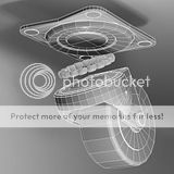
Here are some renders of the final version. You can see that I added the ball bearings and bearing track (race) in the base and swivel pieces. The bearings are very expensive in terms of polygons so I tried to make them dense as needed and then did not smooth them and I also cut off the top and bottom as they would never be seen.

Another solution would be to place a cylindrical ring and apply a alpha + displacement map to simulate the bearings as they would rarely be seen in renders.

user added image user added image user added image user added image user added image


"If I have seen further it is by standing on the shoulders of giants." Sir Isaac Newton, 1675

Last edited by ctbram; 27-08-2011 at 07:48 AM.
# 14 26-08-2011 , 11:57 AM
ctbram's Avatar
Moderator
Join Date: Jan 2004
Location: Michigan, USA
Posts: 2,998
By the way your version is a good first cut. You picked a tricky shape (especially in the swivel part) as a first modeling project.

I would suggest that you add some edge bevels or support edges and smooth the version you have so it does not have such harsh edges. Edge bevels will help catch the light and look more natural. Also, you need to add an axle through the wheel and the fork part.


"If I have seen further it is by standing on the shoulders of giants." Sir Isaac Newton, 1675

Last edited by ctbram; 26-08-2011 at 03:44 PM.
# 15 26-08-2011 , 12:11 PM
ctbram's Avatar
Moderator
Join Date: Jan 2004
Location: Michigan, USA
Posts: 2,998
Here are some tips on modeling the swivel part...

user added image


"If I have seen further it is by standing on the shoulders of giants." Sir Isaac Newton, 1675
Posting Rules Forum Rules
You may not post new threads | You may not post replies | You may not post attachments | You may not edit your posts | BB code is On | Smilies are On | [IMG] code is On | HTML code is Off

Similar Threads