
Introduction to Maya - Rendering in Arnold
This course will look at the fundamentals of rendering in Arnold. We'll go through the different light types available, cameras, shaders, Arnold's render settings and finally how to split an image into render passes (AOV's), before we then reassemble it i
#
16
28-11-2007
, 09:41 AM

Registered User
Join Date: Dec 2005
Join Date: Dec 2005
Location: Brooklyn, NY
Posts: 3,708
#
17
28-11-2007
, 12:41 PM

Registered User
Join Date: Jul 2007
Join Date: Jul 2007
Location: Australia
Posts: 344

It looks great by the way!
Visit www.Notice-Board.co.nz for FREE online classifieds, notices and ads in your area!!
#
18
28-11-2007
, 01:27 PM

Registered User
Join Date: Jun 2004
Join Date: Jun 2004
Location: Gothenburg, Sweden
Posts: 1,318
I had thought about joining again but when I remember it's always like half through.... next time maybe..In other news:
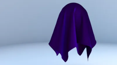
I finished the modeling of the front. So I applied some basic material.
#
19
28-11-2007
, 01:28 PM
Registered User
Join Date: Jun 2004
Join Date: Jun 2004
Location: Gothenburg, Sweden
Posts: 1,318
#
20
28-11-2007
, 01:51 PM
Registered User
Join Date: Jul 2007
Join Date: Jul 2007
Location: Australia
Posts: 344
Visit www.Notice-Board.co.nz for FREE online classifieds, notices and ads in your area!!
#
21
28-11-2007
, 03:47 PM
Registered User
Join Date: Dec 2005
Join Date: Dec 2005
Location: Brooklyn, NY
Posts: 3,708
#
22
28-11-2007
, 10:54 PM
Registered User
Join Date: Jun 2004
Join Date: Jun 2004
Location: Gothenburg, Sweden
Posts: 1,318
#
23
29-11-2007
, 01:08 AM
Registered User
Join Date: Mar 2007
Join Date: Mar 2007
Posts: 1,055
thanks,
gubar
#
24
29-11-2007
, 01:17 AM
Registered User
Join Date: Jun 2004
Join Date: Jun 2004
Location: Gothenburg, Sweden
Posts: 1,318
#
25
29-11-2007
, 03:22 PM

Registered User
Join Date: Mar 2006
Join Date: Mar 2006
Posts: 296
Thanks a lot.

#
26
02-12-2007
, 05:47 PM
Registered User
Join Date: Jun 2004
Join Date: Jun 2004
Location: Gothenburg, Sweden
Posts: 1,318
Last edited by DJbLAZER; 02-12-2007 at 05:49 PM.
#
27
02-12-2007
, 06:23 PM
Registered User
Join Date: Dec 2005
Join Date: Dec 2005
Location: Brooklyn, NY
Posts: 3,708
yeah - i ended up doing something similar for my model as the displacement map was proving to be quite a headache and probably a bit unnecessary for something so small.
cheers mate!
#
28
03-12-2007
, 04:44 AM
Registered User
Join Date: Jun 2004
Join Date: Jun 2004
Location: Gothenburg, Sweden
Posts: 1,318
#
29
04-12-2007
, 03:27 PM
Registered User
Join Date: Mar 2007
Join Date: Mar 2007
Posts: 1,055
Wondering if I can hijack your thread for a bit of quick advice.
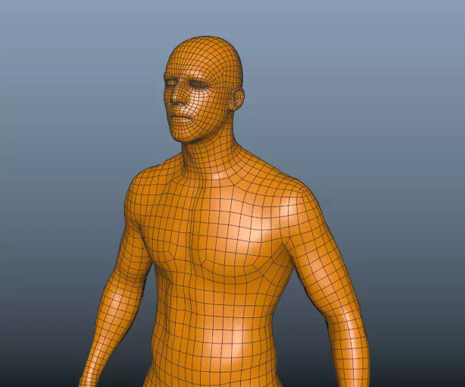
I'm about to start modeling a VCR, so the technique will not be too dissimilar to yours. Say you are modeling the square holes on the body, for where the buttons will go. You'd have at least 4 intersecting lines to dictate the edges of the rectangle, then extrude inwards. To ensure it smooths well, do you have a rule of thumb about adding extra edge loops etc? One at least on either side, on on the inside of the extrusion... am I along the correct lines?
If you could give me a bit of advice and maybe a close up of your mesh on these kind of areas that'd be great.
cheers,
gubar
**EDIT:
I meant' to add, when you're adding the new edge loops, how to you ensure that they're exactly the same distance from the edge (to make sure it's uniform/geometrically exact) - or do you just do it by eye?
Last edited by gubar; 04-12-2007 at 03:36 PM.
#
30
04-12-2007
, 06:41 PM
Registered User
Join Date: Jun 2004
Join Date: Jun 2004
Location: Gothenburg, Sweden
Posts: 1,318
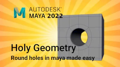
This is how I usually make square wholes:
Posting Rules Forum Rules
Similar Threads
Topics

Free Courses

Full Courses


VFX News
How computer animation was used 30 years ago to make a Roger Rabbit short
On 2022-07-18 14:30:13
Sneak peek at Houdini 19.5
On 2022-07-18 14:17:59
VFX Breakdown The Man Who Fell To Earth
On 2022-07-15 13:14:36
Resident Evil - Teaser Trailer
On 2022-05-13 13:52:25
New cloud modeling nodes for Bifrost
On 2022-05-02 20:24:13
MPC Showreel 2022
On 2022-04-13 16:02:13