Maya for 3D Printing - Rapid Prototyping
In this course we're going to look at something a little different, creating technically accurate 3D printed parts.
# 1 25-06-2011 , 12:13 AM
ctbram's Avatar
Moderator
Join Date: Jan 2004
Location: Michigan, USA
Posts: 2,998

Grumman F8F-1B Bearcat

NOTE: Just a quick note on the images. The top image that got associated with this thread is a f8f-2 model. The f8f-1 models have a 12 inch shorter tail. The last image is a 1B and you can see the difference in the tail height. The rare bear is also a model 2 and I cannot tell what the one in the Blue angle colors is - I want to see model 1 because is what they flew but I see an oil cooler opening at the base of the cowling and that was a model 2 feature. The model 1 had oil cooler flaps just behind the cowling in between the main gear kicker doors.

Started with accurate plans and fuselage cross sections (of course they are in Russian).

user added image

The loft and the tail fairing. I could have done the vertical stab in a single extrusion but the fairing seem to stand out in all the reference images so I decided to model it. I did find that the E-E section was not correctly marked on the side view and had to move it quite a bit forward where it clearly belonged.

user added imageuser added image

Then I modeled the rudder and horizontal stab assembly.

user added imageuser added image

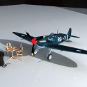
Jumped to the other end and modeled a prop and engine. The Bearcat had 18 cyliners - two rows of 9 cylinders. I started these as just proxies but found adding detail so easy that I just modeled them out. I could add a ton more detail but as you will see almost none of this will be visible for most shots. But since I plan to model the cowl panels I can make some engine shots.

I will add the cylinder cooling fin details with textures as modeling them would make the poly count go insane.

I did most of the engine from eyeballing some open cowling reference images so it's not accurate but will be adequate (in fact it's over detailed) for most shots.

user added imageuser added imageuser added image

All the bits I have so far.

user added imageuser added image

To Do:

- wings
- flaps ailerons
- wheel bays and gear assemblys
- tail wheel, landing hook and misc details
- canopy
- cockpit details

My plan is to model, rig, UV, texture and light this as a complete project. I chose the F8F because I like the aircraft but also because it is not extremely hard to model the gross shapes. Which will allow me to focus on some techniques for modeling the difficult bits like cowl and air frame hatches, cowl flaps, gear doors and bays, etc.

I am not sure if there is a good low poly way to model these as getting the sharp corners for openings becomes a modeling nightmare trying to route all the support edges with out turning the nice surfaces into a lumpy bumpy crap.

I may try an approach I see commonly done in modo and lightwave and max and a dozen other modeling apps, where once I have the low poly done I will smooth and freeze things and then boolean (YES I SAID BOOLEAN) out the door panels and cleanup as best as possible. For parts that I will not be smoothing I will sue edge bevels. Yes! there will most likely be some tri's. But I promise to clean up the ngons (smile).

Attached Thumbnails

"If I have seen further it is by standing on the shoulders of giants." Sir Isaac Newton, 1675

Last edited by ctbram; 07-11-2011 at 03:04 PM.
# 2 25-06-2011 , 10:21 AM
daverave's Avatar
The thin red line
Join Date: Aug 2009
Location: England
Posts: 4,472
Nice to see you back in the saddle, have you got any wire shots please, are you talking about boolean on a high level mesh..........dave


Avatar Challenge Winner 2010
# 3 25-06-2011 , 12:26 PM
ctbram's Avatar
Moderator
Join Date: Jan 2004
Location: Michigan, USA
Posts: 2,998

...are you talking about boolean on a high level mesh..........dave

Yes.

A very common technique I see used in the modo and lightwave forums is to build the base mesh, then smooth to a higher level of detail and freeze the mesh and then trim out the higher level detail parts like hatches and openings.

I constantly struggle to find better ways to put openings into surfaces, especially ones with tight corners, without getting seems, pinching, and lump and bumps into the nice surface I have worked so hard to get as close to G3 as possible.

It seems smoothing and then cutting openings and panels reduces the need to run diagonal edges all over the lower level mesh in an attempt to spread edges that radiate out from tightened corners.

In most examples I have seen a cutter object is created and the openings are booleaned out. Lightwave also has the stencil which is projected on to a surface and can act as a cutter, similar to projecting curves on a maya nurbs surface and then trimming.

Here are some wires of the low res mesh which is at around 34000 polys - 31000 of which are in the engine. Each engine component is very low poly, there are just a lot of components. The engine could have a lot more components but I added only as much detail as needed to get a fairly convincing medium to close shot.

user added imageuser added image

This is an entire area of training that I find missing in all the 3D forums I have read - techniques for creating panels and openings into surfaces that can be smoothed without creating pinching, seems, and surface distortion.

Sure they cover simply surfaces and show how to cut in support edges. But one quickly finds in "real world" models that these approaches are just not practical, unless you cut the entire model into smaller sections to localize the edges needs to cut openings, but then you are faced with trying to match panel / section edges that have different mesh densities.

Since nobody seems willing to share these techniques I am constantly trying to make up my own strategies to solve these surfacing problems in maya, that are handled quite easily in more sophisticated surfacing applications like rhino, solid works, inventor, alias auto, etc..

Example: Look at the top of the horizontal stabalizer (the tail)! Most of those edges are required just to make the upper corner of where the rudder is cut out tight! Also, notice the diagonal edges that have to radiate to the back of the rudder in order to spread the edges out to prevent seems! if you look closely at where I cut out the trim tabs in the elevator there is a seem and pinching and after spending nearly two hours trying I can only minimize it but not completely remove it.

Trying to average verts completely borks hard surface edge flow so it is not an option and god forbid you try to use maya's incredibly bad sculpt surface tool - which I contend should be renamed the "lumpy bumpy **** up your surface beyond all recognition tool", which is probably to long a name but more accurately describes what it does!


"If I have seen further it is by standing on the shoulders of giants." Sir Isaac Newton, 1675

Last edited by ctbram; 25-06-2011 at 05:03 PM.
# 4 25-06-2011 , 09:25 PM
daverave's Avatar
The thin red line
Join Date: Aug 2009
Location: England
Posts: 4,472
I think I saw a bit about maya 2012 that said you can use a curve to cut polygon not sure how true that is?...............dave


Avatar Challenge Winner 2010
# 5 26-06-2011 , 02:53 AM
bullet1968's Avatar
Lifetime Member
Join Date: Feb 2010
Location: Australia
Posts: 4,255
Good to see you back mate...looking bloody exceptional as always my friend. Having had the same problems I usually forgo all the bullshit and bevel as much as I can. When it comes to corners Maya does like to create pain...as you said creates seams where you dont want them. I have also used the split poly tool and stop my lines short of the opposit edge, this of course also creates wierd vert warping...painful stuff.

Good luck with it mate...I will be watching intently

Cheers bullet


bullet1968

"A Darkness at Sethanon", a book I aspire to model some of the charcters and scenes
# 6 27-06-2011 , 08:39 AM
ctbram's Avatar
Moderator
Join Date: Jan 2004
Location: Michigan, USA
Posts: 2,998
Here is a quick test I did on an earlier version of the model. The original plans I used were very inaccurate so I scrapped this version. As a test I smoothed the fuse and wings to 2 levels of linear subdivision and then booleaned out the landing gear panels and the fit is near perfect.

The corners are tight because I made the cutter very quickly and did not smooth any of the corners but smoothing the cutter prior to the Boolean operation will fix this. Since the end model will be smooth to this level of detail anyway I see no problem with the method although I have not considered laying out the uvs yet and what impact this will have no that process.

user added imageuser added image


"If I have seen further it is by standing on the shoulders of giants." Sir Isaac Newton, 1675

Last edited by ctbram; 27-06-2011 at 12:08 PM.
# 7 27-06-2011 , 08:54 AM
bullet1968's Avatar
Lifetime Member
Join Date: Feb 2010
Location: Australia
Posts: 4,255
looks good ct....negative spaces are a biatch!

cheers bullet


bullet1968

"A Darkness at Sethanon", a book I aspire to model some of the charcters and scenes
# 8 29-06-2011 , 12:15 PM
ctbram's Avatar
Moderator
Join Date: Jan 2004
Location: Michigan, USA
Posts: 2,998

Wings and Canopy

Blocked in the canopy and the wings.

user added imageuser added imageuser added image

Wire frame unsmoothed and the 3-key smoothed. I wish there was a way to render the display view contours (i.e., the unsmoothed edges on the smoothed surface when you press the 3-key).

user added imageuser added image

I built the canopy using a cv curve network and a combination of boundary and bi-rail surfaces.

user added image

Added some detail bits ... (hook, tail light, wing blisters, guns)

user added imageuser added image

user added imageuser added imageuser added image

user added imageuser added imageuser added imageuser added image

Now I have to start cutting things up ...

1. canopy frame and glass
2. gear doors, hatches
3. gear asm and wheels
4. cockpit

NOTE: The tail hook is incorrect. I am not sure what the thing in the bottom is but it was the only thing I could get a clear image of and assumed it was the tail hook. I still cannot find any reference material of the actual arrester hook asm.


"If I have seen further it is by standing on the shoulders of giants." Sir Isaac Newton, 1675

Last edited by ctbram; 27-07-2011 at 09:32 AM.
# 9 29-06-2011 , 02:11 PM
honestdom's Avatar
The Nurb Herd
Join Date: Oct 2007
Location: London
Posts: 2,381
Hey man, great modeling as usual.
but how about switching the image planes off or at least make them invisible in reflections.
Also if you are showing off the modelling with a shiny material. how about a turn table or two, even just playblasts will show off the shading better. it might look nice from one angle but reveal a massive bulge from another as i'm sure you know.

# 10 29-06-2011 , 02:33 PM
ctbram's Avatar
Moderator
Join Date: Jan 2004
Location: Michigan, USA
Posts: 2,998
Thanks H. Yeah I have just been tossing a blinn on and doing renders with the reference planes on but did not notice they were distracting. I will clean them up in future uploads.


"If I have seen further it is by standing on the shoulders of giants." Sir Isaac Newton, 1675
# 11 29-06-2011 , 09:30 PM
bullet1968's Avatar
Lifetime Member
Join Date: Feb 2010
Location: Australia
Posts: 4,255
Looking very nice ct! this will be a bewdy when its finished


cheers bullet


bullet1968

"A Darkness at Sethanon", a book I aspire to model some of the charcters and scenes
# 12 01-07-2011 , 06:10 PM
clearairstudios's Avatar
Registered User
Join Date: Jan 2011
Posts: 126
Wow, incredible detail. Look forward to seeing more of this.

Regards

Gary

# 13 01-07-2011 , 10:20 PM
ctbram's Avatar
Moderator
Join Date: Jan 2004
Location: Michigan, USA
Posts: 2,998
Thanks but I have yet to do the detailed modeling. Up to this point it's just the basic main shapes. Now I have to cut in the flaps, ailerons, canopy details, gear doors, various hatches and interior details and I am still deciding on the best approach.

One way would be to smooth to a higher poly count and then cut out the openings. But if I take that approach further smoothing is impossible and I am not sure how difficult it will make uv'ing and texturing.

Option 2 would be to smooth and cut out the various parts and then make the smoothed bits live and rebuild a low poly mesh on top with a clean topology which would be easier to UV and texture and smooth. But without the background constraint concept from modo rebuilding a topology on a live surface is tedious and time consuming.

I would truly wish to meet someone with actual industry experience that could describe a workflow that goes beyond just blocking in basic shapes and then doing everything else with textures and relying on long camera shots.

In years of tinkering with Maya I have yet to see a hi-res hi-detailed hard surfacing tutorial that actually describes cutting detailed openings into smooth surfaces with a high degree of accuracy.


"If I have seen further it is by standing on the shoulders of giants." Sir Isaac Newton, 1675

Last edited by ctbram; 01-07-2011 at 10:28 PM.
# 14 06-07-2011 , 10:31 PM
ctbram's Avatar
Moderator
Join Date: Jan 2004
Location: Michigan, USA
Posts: 2,998
Sorry I am moving kinda slow on this project. I am struggling to decide how to cut the openings into the fuselage. I hate the idea of smoothing 2 divisions and then cutting holes but it seems the only reasonable solution.

Trying to cut holes (especially ones with sharp corners) into a low poly mesh only creates a low poly mess with lots of creases, pinching, lumps and bumps. So I spend a lot of time staring at the screen and scratching my head, but I will move forward eventually.

Modeled the canopy assembly and made some minor tweaks.

user added imageuser added imageuser added imageuser added image

user added imageuser added imageuser added image

To do:
- cockpit
- landing gear
- gear doors
- fuselage panels
- fuselage exhaust opening


"If I have seen further it is by standing on the shoulders of giants." Sir Isaac Newton, 1675

Last edited by ctbram; 07-07-2011 at 03:03 AM.
# 15 08-07-2011 , 05:02 AM
ctbram's Avatar
Moderator
Join Date: Jan 2004
Location: Michigan, USA
Posts: 2,998
Still agonizing over cutting openings so I decided to start working on the gear geometry.

For hard carrier landings the gear carrier based aircraft needed to be longer then land based aircraft. The bearcat is double jointed for this reason. Here is a playblast of the proxy geometry to be sure everything will fit.

YouTube - ‪f8f 19 gear combined‬‏

Another annoyance to add to the Maya 2012 list! It creates ridiculously large playblasts! The original I posted was over 350MB! The one above is a combination of three maya playblasts that were over 700MB combined. Camtasia mp4 got them down to just over 1MB! Nothing like 700:1 compression! lol


"If I have seen further it is by standing on the shoulders of giants." Sir Isaac Newton, 1675

Last edited by ctbram; 08-07-2011 at 06:06 PM.
Posting Rules Forum Rules
You may not post new threads | You may not post replies | You may not post attachments | You may not edit your posts | BB code is On | Smilies are On | [IMG] code is On | HTML code is Off

Similar Threads