Substance Painter
In this start to finish texturing project within Substance Painter we cover all the techniques you need to texture the robot character.
#
106
06-11-2011
, 04:04 AM
Lifetime Member
Join Date: Feb 2010
Join Date: Feb 2010
Location: Australia
Posts: 4,255
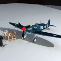
NIce going so far Rick...I like the look of it...wish I had more time myself to get more done on the Spitfire...sadly work in the bush is taking up too much of my life...
cheers bullet
bullet1968
"A Darkness at Sethanon", a book I aspire to model some of the charcters and scenes
#
107
07-11-2011
, 08:08 AM

Moderator
Join Date: Jan 2004
Join Date: Jan 2004
Location: Michigan, USA
Posts: 2,998
thanks, rick
I'd just really like to know what the "official" workflow for incorporating both bump and ao is. My internet search has turned up a Hodge podge of random and sometimes conflicting solutions leaving me scratching my head. The best solution I have found is to pipe the output of the mib_occ+surface_shader into the color slot of a lambert+bump. Using the amb color did not seem to work (I got no occlusion).
The method of putting the ss colorout into a lambert+bump works but to fix the diff color on the remaining parts I have to pump the ss colorout into a regular lambert with no bump and put that on all the remaining bits in the scene and then all the diff color matches. The result, to me, looks like a ao render composited with a normal render. It also takes a long time to render. I felt the single render time was longer then just rendeing the ao and normal renders separately.
There is also a custom utility node called layer20xxx, and BumpCombiner for mental ray that allow you to add a bump slot to nodes that do not have them. I have installed BumpCombiner but have not figured out how to use it.
"If I have seen further it is by standing on the shoulders of giants." Sir Isaac Newton, 1675
Last edited by ctbram; 07-11-2011 at 08:19 AM.
#
108
07-11-2011
, 09:55 AM

The Nurb Herd
Join Date: Oct 2007
Join Date: Oct 2007
Location: London
Posts: 2,381
The only problem i think people have on this forum is that they generally don't know what they are going to do for a final shot. No one seems to do any layout, its just tumble tumble render done.
...actually the other thing that people do for the cool factor is post over the top WIP images. I'm sure i've seen someone post a screenshot of their image planes.

EDIT: oops, wasn't reading the last page.
Last edited by honestdom; 07-11-2011 at 09:58 AM.
#
109
07-11-2011
, 10:48 AM

The thin red line
Join Date: Aug 2009
Join Date: Aug 2009
Location: England
Posts: 4,472
 ................dave

Avatar Challenge Winner 2010
Last edited by daverave; 07-11-2011 at 11:00 AM.
#
110
07-11-2011
, 11:12 AM
Moderator
Join Date: Jan 2004
Join Date: Jan 2004
Location: Michigan, USA
Posts: 2,998
Those image planes are there for a reason and show how the model is progressing relative to the reference. They are also intended to show how I modeled the plane and not just what I can model. I see these threads as more then just "look at what I can do" but also "here is how I did it". Therefore, the image planes serve a purpose and I do not believe they are over the top at all, in fact, I happen to like they way they look even beyond the practical reasons.
"If I have seen further it is by standing on the shoulders of giants." Sir Isaac Newton, 1675
Last edited by ctbram; 07-11-2011 at 11:36 AM.
#
111
07-11-2011
, 11:37 AM
The Nurb Herd
Join Date: Oct 2007
Join Date: Oct 2007
Location: London
Posts: 2,381
I didn't mean aNYone in particular. I didn't look at the start of this thread and see you had rendered your image planes. I WASn't making fun of you if thats what you were thinking. I was talking generally.
You are right, there are no rules for posting in a WIP thread. I JUST find it funny when people render THINGS AFTER a couple of hours MODellinG and present them really nicely with logos and borders and whatever. Its not just this forum that it happens on. I dont see the point.
yes, its just my opinion.
#
112
07-11-2011
, 01:35 PM

Lead Modeler - Framestore
Join Date: Feb 2003
Join Date: Feb 2003
Location: UK
Posts: 6,287
Opinions are like assholes, everybody has one.
Dom: do they not do model to reference turntables etc where you work??
Jay
#
113
07-11-2011
, 02:04 PM
The Nurb Herd
Join Date: Oct 2007
Join Date: Oct 2007
Location: London
Posts: 2,381
we do model and reference dailies but they are usually about 90% finished.
#
114
08-11-2011
, 12:16 AM
Moderator
Join Date: Jan 2004
Join Date: Jan 2004
Location: Michigan, USA
Posts: 2,998
"If I have seen further it is by standing on the shoulders of giants." Sir Isaac Newton, 1675
Last edited by ctbram; 08-11-2011 at 06:29 AM.
#
115
08-11-2011
, 06:02 AM
Moderator
Join Date: Jan 2004
Join Date: Jan 2004
Location: Michigan, USA
Posts: 2,998
I either get the gear in the gear bay properly and they extend all twisted or I get them extended correctly and then they do not sit in the gear bay properly!
This is a nightmare! I must have spent 12 hours today noodling with it and it's just an intractable problem!
I can see in the references there are just two single hinge joints. I do not see how the hell they can possibly extend AND twist the gear! But they have to twist because there is no room for them to sit in the bay without twisting up at the leading edge! I checked and rechecked the scale of the wheels and the wing section and the gear have to twist!
By twist I mean when they are down they wheels of course must be facing straight forward and when they are retracted the need to rotate such that the wheel is higher at the leading edge.
I'm calling it a night I will work more on it this weekend. I will have to make a inventor or solidworks model or simulink model and work the linkage out mathematically because trial and error is going to give me a stroke.
"If I have seen further it is by standing on the shoulders of giants." Sir Isaac Newton, 1675
Last edited by ctbram; 08-11-2011 at 06:20 AM.
#
116
08-11-2011
, 07:49 AM
The thin red line
Join Date: Aug 2009
Join Date: Aug 2009
Location: England
Posts: 4,472
Edit:I do know that it folds in on its self but you need to find the first joints Orientation
Avatar Challenge Winner 2010
Last edited by daverave; 08-11-2011 at 09:17 AM.
#
117
08-11-2011
, 11:59 AM
Moderator
Join Date: Jan 2004
Join Date: Jan 2004
Location: Michigan, USA
Posts: 2,998
The upper portion of the gear rotates outward and the lower rotates inward (kinda like scissors). But that upper part has a twist in it that is impossible to see clearly from the reference images that causes the gear to twist as they extend and retract (cycle).
"If I have seen further it is by standing on the shoulders of giants." Sir Isaac Newton, 1675
Last edited by ctbram; 08-11-2011 at 12:19 PM.
#
118
08-11-2011
, 01:25 PM
Moderator
Join Date: Jan 2004
Join Date: Jan 2004
Location: Michigan, USA
Posts: 2,998
"If I have seen further it is by standing on the shoulders of giants." Sir Isaac Newton, 1675
#
119
08-11-2011
, 01:26 PM
Lead Modeler - Framestore
Join Date: Feb 2003
Join Date: Feb 2003
Location: UK
Posts: 6,287
when in a situation like this have a look at model kits https://modelingmadness.com/reviews/a...jacksonf8f.htm worth it.
Jay
#
120
08-11-2011
, 01:29 PM
Moderator
Join Date: Jan 2004
Join Date: Jan 2004
Location: Michigan, USA
Posts: 2,998
Ah you even included a link to the kit! Thanks again and it's a whole seven bucks! lol... Well worth the hours of agony I have spent trying to figure it out by trial and error.
The funny thing is that it looks so simple in the references. But I am finding just very tiny changes in the orientation and rotation pivot on that base piece make radical changes to the orientation of the gear between the up and down positions. I start in the down position oriented correctly and was then systematically making changes to the rotation pivot of the upper part. The lower part has to always be the same.
"If I have seen further it is by standing on the shoulders of giants." Sir Isaac Newton, 1675
Last edited by ctbram; 08-11-2011 at 01:34 PM.
Posting Rules Forum Rules
Similar Threads
F8F Bearcat
by Miercoles in forum Work In Progress replies 22 on 14-09-2004
Mech Warrior Movie 1B?
by rahaney in forum SimplyMaya Tutorials replies 0 on 16-11-2003
The ugly duckling Grumman J2F-6
by undseth in forum Work In Progress replies 95 on 18-03-2003
FinalGathering of the Grumman Duck
by undseth in forum Lighting & Rendering replies 3 on 09-02-2003
Topics


Free Courses


Full Courses


VFX News
How computer animation was used 30 years ago to make a Roger Rabbit short
On 2022-07-18 14:30:13
Sneak peek at Houdini 19.5
On 2022-07-18 14:17:59
VFX Breakdown The Man Who Fell To Earth
On 2022-07-15 13:14:36
Resident Evil - Teaser Trailer
On 2022-05-13 13:52:25
New cloud modeling nodes for Bifrost
On 2022-05-02 20:24:13
MPC Showreel 2022
On 2022-04-13 16:02:13